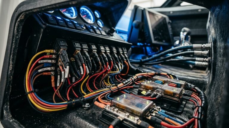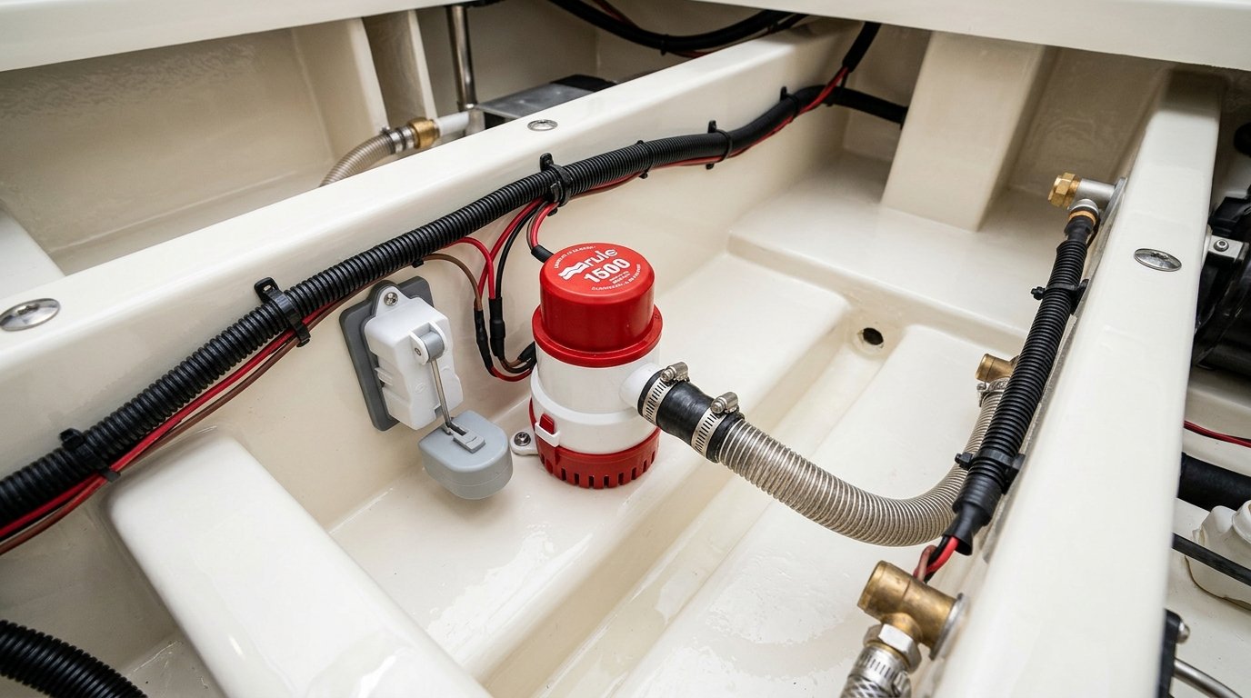
An automatic bilge pump is your vessel’s primary defense against sinking at the dock or taking on green water in heavy seas. Executing proper boat bilge pump wiring with float switch ensures that your pump activates instantly when rising water lifts the mechanical float switch—even when you are miles away from the marina and the boat battery selector switch is turned to “OFF”.
Every year, thousands of unattended boats swamp at moorings due to dead batteries, corroded wire nuts, or incorrectly wired switches that disable the automatic float sensor when the captain leaves the dock. Understanding the principles of boat bilge pump wiring with float switch gives you complete confidence that your submersible pump will run reliably in both automatic float mode and manual helm override. Below, certified marine electricians break down the standard 3-wire installation diagram.
How a 3-Wire Bilge Pump & Float Switch Circuit Operates
Modern submersible marine bilge pumps (such as Rule, Johnson, or Attwood) paired with an external float switch or featuring internal solid-state water-sensing electronics utilize a 3-conductor electrical circuit. When designing your boat bilge pump wiring with float switch, understanding how the three operational modes function is vital:
| Switch Setting | Circuit Path & Power Source | Operational Function |
|---|---|---|
| AUTOMATIC Mode | Direct battery positive (+) through float switch to pump | Pump activates automatically when water lifts the float switch 2 inches; shuts off when water drops to 0.75 inches. |
| MANUAL Override | Switched 12V DC feed directly from helm switch to pump | Spring-loaded momentary toggle forces pump to run continuously regardless of float switch position. |
| OFF Position | Cuts manual switched feed (Automatic circuit remains live if wired correctly) | Prevents continuous pump dry-running if debris jams the mechanical float switch in the “up” position. |
The Golden Rule of Bilge Safety: According to electrical standards published by the American Boat and Yacht Council (ABYC E-11), the automatic float switch circuit must be wired directly to the ungrounded positive battery terminal with an inline fuse located within 7 inches of the battery. It must never be routed through the main battery selector switch.
Standard 3-Wire Boat Bilge Pump Wiring Diagram
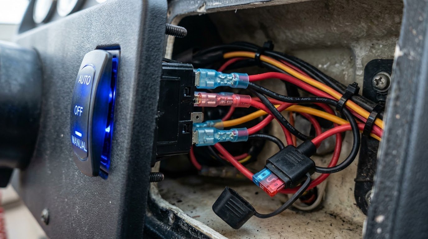
To wire a submersible pump with a separate float switch and a 3-way helm dash switch (AUTO-OFF-MANUAL), connect the conductors as follows:
- DC Negative Ground (Black): Connect the black wire from the bilge pump motor directly to the boat’s common negative DC ground busbar or the negative battery post.
- Automatic Positive Circuit (Brown/White): Run an unswitched 14 AWG tinned marine wire directly from the battery positive terminal, through a marine-grade waterproof fuse holder, to one lead of the float switch. Connect the second lead of the float switch to the brown (positive) wire on the pump motor.
- Manual Override Circuit (Brown): Run a separate 14 AWG tinned wire from the manual terminal of your helm dash rocker switch directly to the pump motor’s brown positive wire, splicing it together with the float switch output wire.
- Indicator Light: Connect the terminal of the helm switch’s internal amber indicator light to the brown pump wire so the dash light illuminates whenever the pump runs—whether triggered by the float switch or manual toggle.
Wire Sizing, Fusing & Submersible Splice Protection
Because the bilge compartment is constantly damp, oily, and subject to standing water, executing durable boat bilge pump wiring with float switch demands specialized materials:
| Pump Capacity (GPH) | Current Draw (Amps) | Recommended Fuse Size | Minimum Wire Gauge (Up to 20ft run) |
|---|---|---|---|
| 500 – 800 GPH | 2.5 – 3.5 Amps | 5 Amp ATO/ATC | 16 AWG Tinned Copper |
| 1,000 – 1,500 GPH | 4.5 – 7.0 Amps | 10 Amp ATO/ATC | 14 AWG Tinned Copper |
| 2,000 – 3,700 GPH | 12.0 – 15.5 Amps | 20 Amp ATO/ATC | 12 AWG or 10 AWG Tinned Copper |
Never Use Twist-On Wire Nuts: Household twist-on wire nuts corrode into green copper dust within weeks in a boat bilge. Always use adhesive-lined heat-shrink butt connectors crimped with a ratcheting tool, followed by an outer layer of dual-wall adhesive heat-shrink tubing to create an airtight, 100% waterproof seal.
For complete DC wiring standards, consult our marine electrical systems 101 guide, our marine battery care guide, and our marine dual battery switch wiring guide.
Frequently Asked Questions About Boat Bilge Pump Wiring with Float Switch
Why does my bilge pump fuse keep blowing when the float switch activates?
The most common cause is debris (fishing line, wood splinters, or hair) wrapped tightly around the centrifugal pump impeller inside the plastic strainer housing. When the float switch activates, the jammed motor cannot turn, drawing locked-rotor current that blows the fuse within two seconds. Clean the impeller housing before replacing the fuse.
Can an automatic bilge pump drain my battery completely while docked?
Yes. If your boat has a small rainwater leak or a leaking through-hull fitting, a pump cycling every 5 minutes will deplete a healthy 100Ah marine battery within 24 to 48 hours. Consider installing an auxiliary solar battery maintainer or a bilge cycle counter to track pump activity.
What is the difference between a mechanical float switch and an electronic water sensor?
Mechanical float switches rely on a hinged plastic arm with an internal ball switch that floats upward with rising water. Electronic water sensors (such as field-effect or ultrasonic sensors) have zero moving parts and cannot jam from oil sludge or debris, making them significantly more reliable in dirty bilges.
Where should the float switch be mounted in relation to the pump?
Mount the float switch approximately 1/2 to 1 inch above the base level of the pump strainer. This ensures that minor condensation puddles in the bilge bottom do not trigger constant short-cycling, while guaranteeing the pump primes with water before the float switch trips.
Published by Boat Maintenance Guide Electrical Systems Desk. Inspected in accordance with American Boat and Yacht Council (ABYC) E-11 AC and DC Electrical Systems on Boats and H-22 Bilge Pump Systems standards.